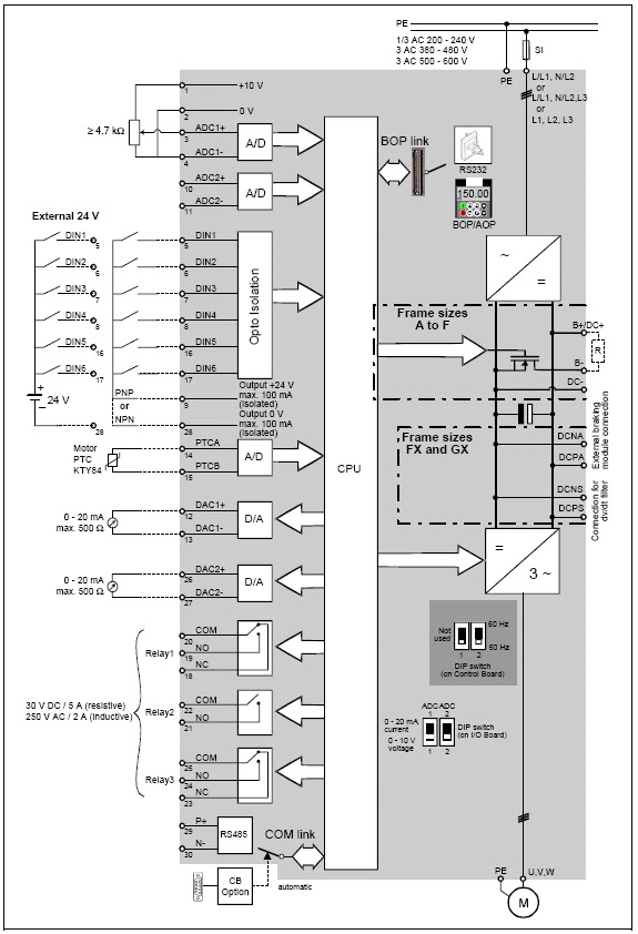
Vfd Pump Wiring Schematic
Vfds improve motor & pump control Vfd diagram plc wiring control circuit schematic drive using ladder diagrams connections logic Wiring diagram for vfd
VFDs Improve Motor & Pump Control | Pumps & Systems
Output vfd board cnc spindle planet wiring control diagram controlling motor speed schematic circuit connect phase inputs single symbols direction Vfd variable pwm Vfd drive variable frequency ac drives diagram circuit motor igbt electrical schematic phase working control three operation works speed dc
Vfd variable speed motor drive ac diagram installation block switches controlled control frequency connected function phase drives controller terminals components
Pump control motor vfd lag pressure pumps line motors vfds improve across figure automation withoutVfd inverter Plc vfd circuitsLearn how to use plc and vfd for pump control: power and control.
Understanding vfd circuitWiring diagram vfd drives basic acs550 s10 circuit abb ac drive electrical adapter control radar Abb vfd wiring diagramVfd wiring practicalmachinist lathes installations starter.

Vector vfd
Single phase variable frequency drive vfd circuitVfd diagram wiring circuit drive variable frequency types Vfds improve motor & pump control (page 2)Allen bradley motor control wiring diagrams.
Pump vfds vfd pumps multiplexVfd controlled by switches Wiring diagram for vfdVfd circuit diagram schematic wiring motor understanding drive variable frequency components vfds output rectifier fig resolution click.

Vfd wiring diagram motors phase l2 l1 input wire single circuit ground terminal schematic 220v three diagrams chassis
Vfd application working vfds implementation drive frequency variable principleWiring diagram for vfd Vfd wiring diagram probotix huanyang wiki spindle wire power speed controller output board 10v pixels mill originalVfd wiring contactor patents.
101 electrical engineering interview topics: variable frequency driveVfd wiring electrical principle Vfd use backups bypasses exclusive should web whichVfd control panel wiring diagram.

Vfd diagram drive block variable frequency control topics electrical engineering interview
Vfd wiring diagram control circuit schematic output programming spindle symbols diagrams using cnc boardWiring diagram for vfd Vfd or inverter drive power component schematicWiring diagram for vfd.
Brief explaination about working of vfds, benefits and applicationPatent us6650245 .


Learn how to use PLC and VFD for pump control: Power and control

Understanding VFD circuit

VFD Controlled by Switches

101 Electrical Engineering Interview Topics: Variable Frequency Drive

VFDs Improve Motor & Pump Control (Page 2)

VFDs Improve Motor & Pump Control | Pumps & Systems

wiring diagram for vfd - Wiring Diagram and Schematic
Vfd Control Panel Wiring Diagram - Electrical Wiring Diagrams